Decks
Construction guidelines for non-sheltered decks for residential dwellings
GENERAL INFORMATION
NOTE: Throughout this booklet the Manitoba Building Code will be referred to as the Building Code.
Decks vary in size and area and it is beyond the scope of this publication to deal with each possible situation. The Portage la Prairie Planning District requirements and construction guidelines that follow are provided to only assist you in designing and constructing a deck which will comply with the regulations.
The ultimate responsibility for compliance rests with the owner.
Do I require a building permit for a deck?
YES! A building permit is required for any deck which is higher than one riser (approximately 200 mm/8 in.) above average ground level or any deck which will eventually support an enclosed structure with a roof such as a sun room, family room, etc. This applies to all decks even if they are not attached to any structure.
Are overhead power supply conductors or Hydro meters a cause for concern? YES! For information on overhead height requirements or location of Hydro meter contact your local Manitoba Hydro District Operating Centre at the phone number listed on your Manitoba Hydro invoice.
What information do I have to bring with me in order to make application for a building permit?
You must present one copy of a Surveyor’s Building Location Certificate.
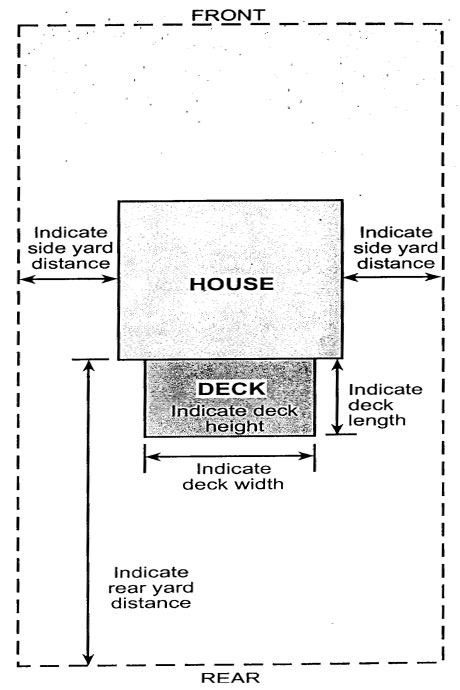
As an alternative, a well drawn site plan showing all property dimensions, location of all buildings and the location and size of the proposed deck may be acceptable. See Figure A.
|
Figure A
|
What do the construction and elevation plans have to indicate?
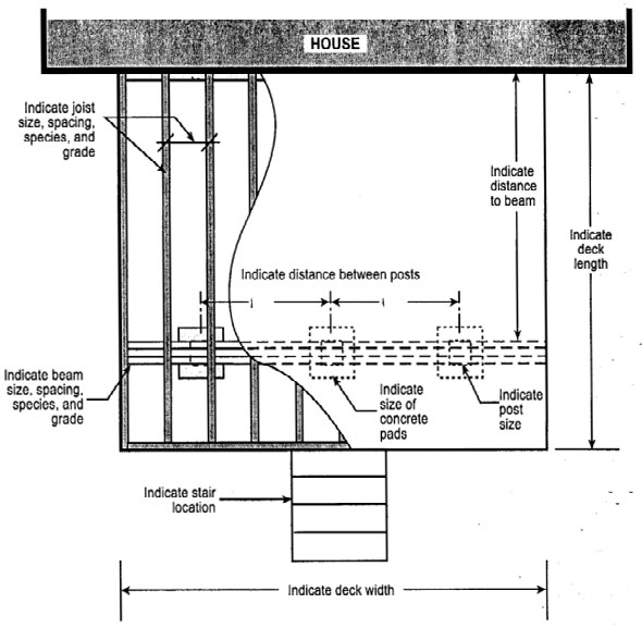
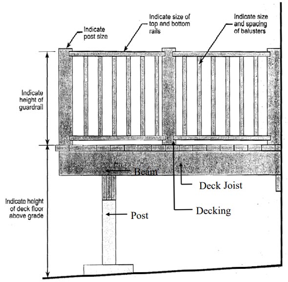
The construction plans must show the size of the deck, the size and spacing of the beams, posts and floor joists, the species and grade of material being used, the type of foundation you have chosen to support the deck and the location of any stairs leading to or from the deck. The elevation plan must show the height of the deck floor above finished ground level at its highest point and the height and type of guardrail being used around the perimeter of the deck. See Figures B and C.
|
If I cannot meet the zoning requirements, what are my alternatives?
Change the location; Change the size;
OR
Vary the requirements by applying for a Zoning variance. This application can be made at the Portage la Prairie Planning District office.
FOUNDATION
Open Decks under 1200 mm (4 ft.) in Height Surface Pad Foundations
Surface pad foundations only permitted when an open deck is:
a) not more than one storey;
b) not more than 55msq. (592 ft sq) in area;
c) not more than 1200 mm (4 ft) in distance from finished ground to the underside of the joist;
d) not supporting a roof, and
e) not attached to another structure, unless it can be demonstrated that differential movement will not adversely affect the performance of that structure, as determined by the authority having jurisdiction.
When using surface foundations, access must be provided to the foundation to permit re-levelling of the deck platform. It can be provided either by:
a) a passageway with a clear height and width under the deck platform of not less than 600 mm (2 ft); or
b) by installing the decking in a manner that allows easy removal (i.e. screws)
If your long range plans are to enclose all or a portion of your deck with a screened-in area, sunroom, or extension to your dwelling, and the enclosed area will be attached to the main dwelling via the walls or the roof, it is suggested that you use an approved foundation as described further in this pamphlet, or that your retain a Professional Engineer registered in the Province of Manitoba to design an adequate foundation.
Should you decide to retain an Engineer, bring two (2) copies of the Engineer’s design under seal and signature when applying for your building permit.
|
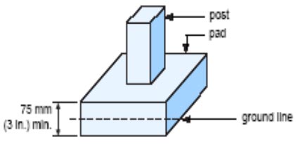
Figure 1
|
What are the recommendations for a surface pad foundation?
Surface pads should be made of concrete or other material which will not prematurely deteriorate as a result of contact with the soil. As shown in FIGURE 1, they should be a minimum 75mm (3 in.) thick and be installed so that the top surface is slightly above adjacent finished ground level in order to prevent premature deterioration of the post or beam which will be bearing on the pad.
Refer to TABLE 1 to determine the recommended foundation pad size. Foundation pads are available at most lumber dealers.
| TABLE 1 - Recommended Deck Foundation Pad Sizes (1) | |
| Maximum Supported Joist Length (2) | Concrete Surface Pad Size (length x width x thickness) |
| 1.22 m (4 ft) | 300mm x 300mm x 100mm (12 in. x 12 in. x 4 in.) |
| 3.05 m (10 ft.) | 450mm x 450mm x 75mm (18 in. x 18 in. x 3 in.) |
| 4.88 m (16 ft.) | 600mm x 600mm x 150mm (24 in. x 24 in. x 6 in.) |
NOTES to TABLE 1:
- This table requires beams with supports every 2.44 m (8 ft.) or less.
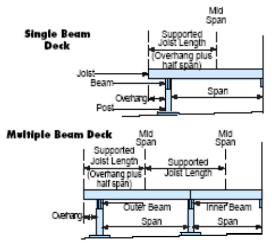
- Supported joist length means half the span of joists supported by the beam plus the length of the overhang beyond the beam. See Figure 4.
Open Decks Over 1200 mm (4 ft) in Height - Pile or Pier Foundations
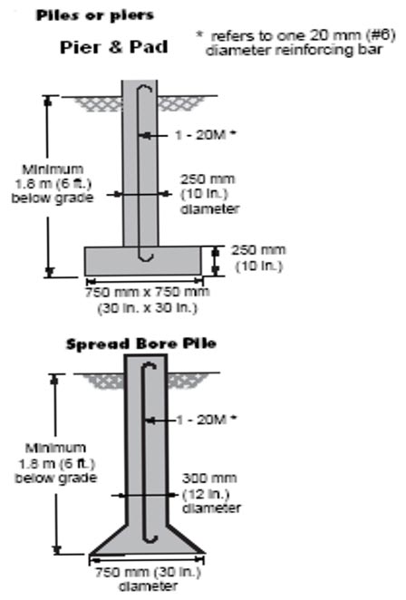
When the underside of the deck joists are more than 1200 mm (4 ft) above the ground, the foundation depth must be at least the depth of frost penetration - 1.8 m (6 ft). A pier or pile type foundation, as shown in FIGURE 2, or alternatively a foundation designed by a Professional Engineer is required.
|
Figure 2
|
What other options are available?
A foundation using “ground anchors” may be permitted providing the anchor extends to below the depth of frost penetration and has been properly tested. You may need to retain someone to do load calculations to determine that the loads transferred to the foundation does not exceed the loads for the tested anchors. If your future plans are to enclose the deck with a sunroom, screened patio, etc. the type of “ground anchors” must be approved for sunroom, screened patio, etc. uses.
How far apart can these pads, piles, or piers be installed?
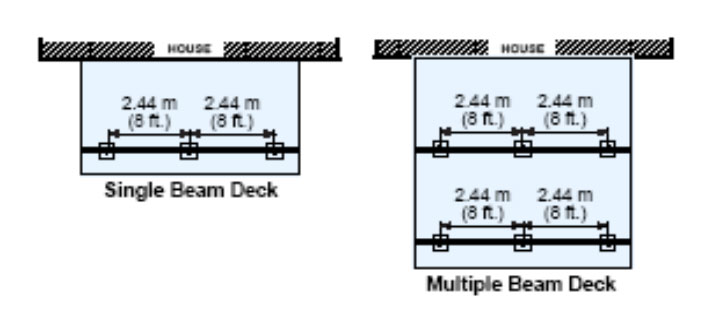
The location of the pads, piles, or piers can vary depending on the size and the type of material used for the beam that spans from one pad, pile, or pier to the other; and the amount of floor area that each individual pad, pile, or pier is required to carry. The examples shown in FIGURE 3 are based on the beam supports having a maximum spacing of 2.44 m (8 ft.) on centre. The beam table that follows indicates beams which are adequate for this spacing.
|
Figure 3
|
Can I vary from this 2.44 m (8 ft.) spacing?
Yes, you can place the pads, piles, or piers closer together and still maintain the beam sizes used in this publication for 2.44 m (8 ft.) spacing. Alternatively, if you wish to place them further apart, you would have to install a beam which is adequate for that longer span. The beam sizes indicated in this publication have been calculated using common engineering principles. Other variations are possible provided the deck is designed and installed to carry a live load of 1.9 kPa (40 psf).
If you wish to increase the spacing of the pads, piles, or piers, or if you wish to reduce the beam sizes indicated in the beam tables, you have to retain someone who is familiar with the required engineering calculations. Whichever design you choose, it must be indicated on your plans at the time of your building permit application.
Can I use multiples of the 2.44 m (8 ft.) spacing and make my deck deeper and/or wider?
Yes you can, provided you continue to meet all of the same construction requirements and provided you do not exceed the area that is permitted for your particular property.
What size posts should I use and how should they be anchored?
Posts, if used, should be at least the width of the beam, centered on the pad, pile, or pier, and securely fastened to the beam by means of toe nailing, wood gussets, angle brackets, or other equivalent methods. Where posts exceed 1.22 m (4 ft.) in length, they should be braced to each other, or up to the beam and floor, or alternatively, they should be anchored to the pad, pile, or pier in order to prevent them from shifting at the bottom.
What size of beams do I need? The beam table, (TABLE 2), is intended for single beam decks and multiple beam decks having supports at 2.44 m (8 ft.) intervals along the beam. See also Figure 4.
| TABLE 2 Deck Beam Sized (1) Design Floor Live Loads for 1.9 kPa (40 psf) |
|
| Maximum Supported Joist Length (2) | Beam Size (3) |
| 2.44 m (8 ft.) | 3 - 38 x 140mm or 2 - 38 x 184mm (3 - 2 x 6 or 2 - 2 x 8) |
| 3.05 m (10 ft) | 4 - 38 x 140mm (4 - 2 x 6) |
| 3.66 m (12 ft) | 3 - 38 x 84mm or 2 - 38 x 235mm (3 - 2 x 8 or 2 - 2 x 10) |
| 4.27 m (14 ft) | 4 - 38 x 184mm (4 - 2 x 8) |
| 4.88 m (16 ft) | 3 - 38 x 235mm or 2 - 38 x 286mm (3 - 2 x 10 or 2 - 2 x 12) |
NOTES to TABLE 2:
- This table requires beams with supports every 2.44 m (8 ft.) or less.
- Supported joist length means half the span of joists supported by the beam plus the length of the overhang beyond the beam. See Figure 4.
- This table is for use with Spruce-Pine-Fir lumber grades 1 and 2.
Can I have joints in the beam?
Yes. However, when joints are necessary, they should be situated on a support (post). On multiple-ply laminated beams the joints should be staggered so that joints occur on alternate supports.
If it is intended to project the beam beyond the end supports, there should be no joints on the end support.
How far can I project the beam beyond the end support?
The beam can project a maximum of 600mm (2 ft) beyond the end support.
STRUCTURAL
How far can the joists project beyond the face of the outside beam?
If you are planning to eventually enclose all or a portion of the deck with a roofed structure which could carry snow, the Building Code states the joists can only project 400 mm (16 in.) where 2 x 8 joists are used, and 600 mm (2 ft.) where 2 x 10 or larger joists are used. The projection of 2 x 6 joists would require engineering analysis to determine if the floor assembly would be sufficient to carry the super-imposed roof loads.
|
Figure 4
|
Do the deck members need to be pressure treated?
When the vertical clearances between the wood elements and the finished ground level is less than 150mm (6 in.) or when the wood elements are not protected from exposure to precipitation, they must be pressure treated with a preservative to resist decay.
What size of floor joists do I require?
The size of the floor joists are governed by the distance they have to span, and the spacing at which the floor joists are installed. TABLE 3 indicates some common species and sizes of wood and the acceptable span distances for wood decks. Joist spans are measured from face of support to face of support (in case of a wood deck, from face of beam to face of beam, or face of beam to face of ledger).
Another item you should take into consideration when selecting the type, size, and spacing of your floor joists is the type of material that you intend to use as decking. Check with your lumber dealer to ensure that the decking you select will not sag significantly between the joists as a result of the joist spacing you have chosen.
| TABLE 3 Deck Floor Joist Spans Design Floor Live Loads for 1.9 kPa (40 psf) |
|||||||||
| Commercial Designation | Grade | Member Size (In.) | Joist Spacing | Member Size (mm) | Joist Spacing | ||||
| 12 in ft - in |
16 in ft - in |
24 in ft - in |
300mm m |
400mm m |
600mm m |
||||
| Douglas Fir - Larch | No.1 and No.2 | 2 x 4 2 x 6 2 x 8 2 x 10 |
8 - 6 13 - 5 16 - 7 20 - 4 |
7 - 9 11 - 10 14 - 4 17 - 7 |
6 - 9 9 - 8 11 - 9 14 - 4 |
38 x 89 38 x 140 38 x 184 38 x 235 |
2.59 4.08 5.06 6.19 |
2.36 3.60 4.38 5.36 |
2.05 2.94 3.58 4.38 |
| Spruce Pine Fir | No.1 and No.2 | 2 x 4 2 x 6 2 x 8 2 x 10 |
8 - 1 12 - 9 16 - 9 21 - 5 |
7 - 4 11 - 7 15 - 3 19 - 1 |
6 - 5 10 - 1 12 - 9 15 - 7 |
38 x 89 38 x 140 38 x 184 38 x 235 |
2.47 3.89 5.11 6.52 |
2.24 3.53 4.64 5.82 |
1.95 3.08 3.89 4.75 |
| Column 1 | 2 | 3 | 4 | 5 | 6 | 7 | 8 | 9 | 10 |
NOTES to TABLE 3:
This table applies to outdoor decks above grade only, and assumes a minimum of 1 inch decking material. The figures in this table do not correspond to those found in Appendix A of the National Building Code, (Floor Joist and Built-up Floor Beams).
Are there any requirements for stairs?
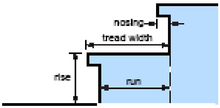
The Building Code requires that treads and risers have uniform rise and run in any one flight, with riser heights not exceeding 200 mm (8 in.). The Building Code also requires the minimum run of each tread to be 210 mm (8 1/4 in.) and the minimum tread width to be 235 mm (9 1/4 in.). See Figure 5 for details.
|
Figure 5
|
IF: The run is 210mm (8 1/4 in.)
THEN: A nosing of at least 25mm (1 in.) must be provided.
What is the difference between guardrails and handrails?
Guardrails are intended to prevent persons from falling off the edge of a stair or a raised floor area such as a deck. The guardrail must be able to withstand the pressure of a human body applied horizontally against it. Handrails are required to assist persons in ascending ordescending stairs. They offer a continuous handhold to support persons who may stumble on the stairs.
Will my deck require guardrails?
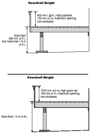
The need for guardrails is determined according to the height of the deck floor surface above the finished ground level as follows:
- Decks with floor surfaces that do not exceed 600 mm (2 ft.) above the finished ground level at any point around their perimeter do not require guardrails.
- Decks with floor surfaces which are more than 600 mm (2 ft.) but not more than 1.8 m (6 ft.) above the finished ground level at any point around their perimeter require a guardrail at least 900 mm (36 in.) in height. See Figure 6A.
Openings to the underside of the top horizontal member of the guardrail must be such as to prevent the passage of a spherical object having a diameter of 100 mm (4 in.) - Decks with floor surfaces which are more than 1.8 m (6 ft.) above finished ground level at any point around their perimeter require a guardrail at least 1070 mm (42 in.) in height. See Figure 6A. Openings to the underside of the top horizontal member of the guardrail must be such as to prevent the passage of a spherical object having a diameter of 100 mm (4 in.).
There must be no member or attachment between 100 mm (4 in.) and 900 mm (36 in.) measured from the floor surface of the deck which will facilitate climbing.
|
Figure 6A
|
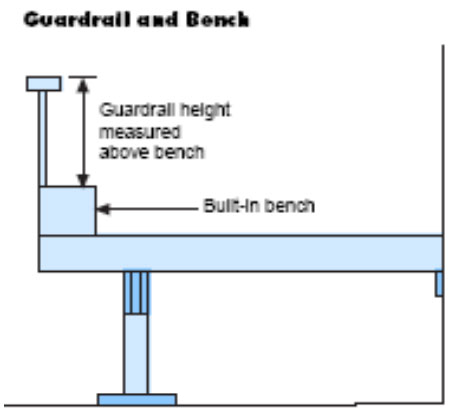
Can a built-in bench serve as a guardrail?
No, unless a guardrail meeting the previously described height and opening requirements is provided above the flat surface of the bench and any openings below the bench also meet the maximum opening requirements. See FIGURE 6B.
|
Figure 6B
|
What is the difference between a built-in bench and a chair or a table?
If a chair or a table are in a hazardous position, you have the option of moving them. A built-in bench does not give you that option.
Are guardrails required for stairs?
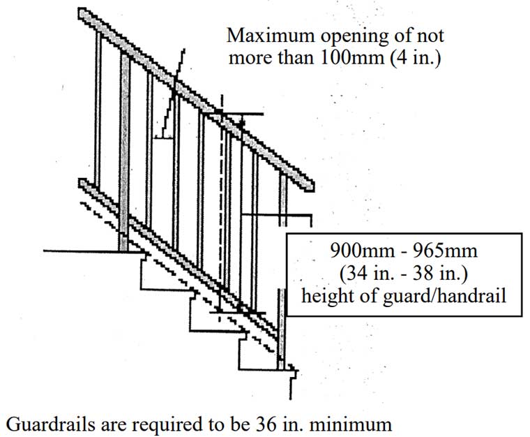
Stairs which have more than three (3) risers and which exceed 600 mm (2 ft.) above the finished ground level also require guardrails. These guards are to be at least 900 mm (36 in.) in height measured vertically above a line drawn through the outside edges of the stair nosing. If the stairs have an
intermediate landing, the guardrail must be at least 900 mm (36 in.) in height over the landing area. Openings situated below these heights are to be such as to prevent the passage of a spherical object having a diameter of 100 mm (4 in.).
Will the stairs also require a handrail?
The Building Code states that if any outside stairs have more than three (3) risers, a handrail is required on one side of the stairs. As shown in Figure 7, the handrail is required to be a minimum of 900 mm (36 in.) in height measured vertically above a line drawn through the outside edges of the stair nosing. Stairs with three (3) risers or less do not require handrails. In those cases where stairs also requires a guardrail, a reasonable solution is to provide a guardrail, which also acts as a handrail.
|
Figure 7
|
Every effort has been made to ensure the accuracy of the information contained on this page. However, in case of a discrepancy between this information and the respective By-laws, the By-law will take precedence.
Please contact us for further information.
This website uses cookies to understand your use of our website and to give you a better experience. By continuing to use the site or closing this banner, you agree to our use of cookies. To find out more about cookies and how to change your choices, please go to our Privacy Policy.


